
GamePi NanoCab building
A new project...
Dear readers, I will share with you my new project, which began recently, and still in progress.
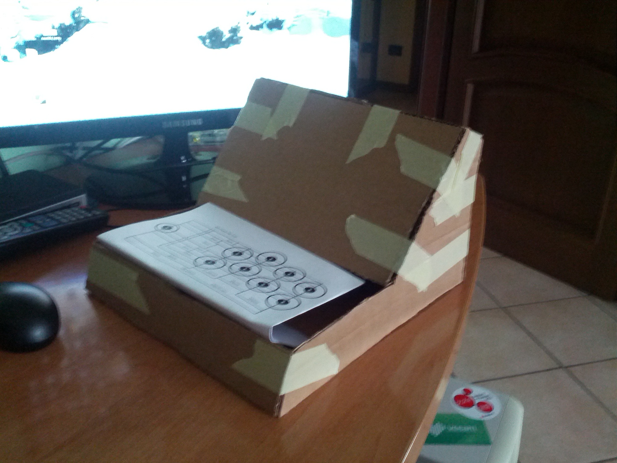
My idea is to build a NanoCab, an Arcade Cabinet as those who were once, and animate it with a Raspberry inside. Obviously the size will be like those of raspberry, mini!! I have already made a prototype board of approximate dimensions in order to calculate the various dimensions and layout.
Here come the first pieces!
The postman begins to bring me the first pieces arriving from the UK. I bought everything online, and have already arrived joystick, buttons, wires, connectors and screen.
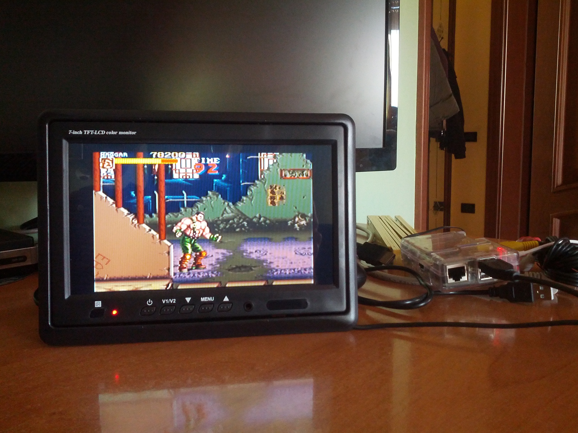 Lets start from the screen, is a 7-inch LCD, found on ebay for 30€.
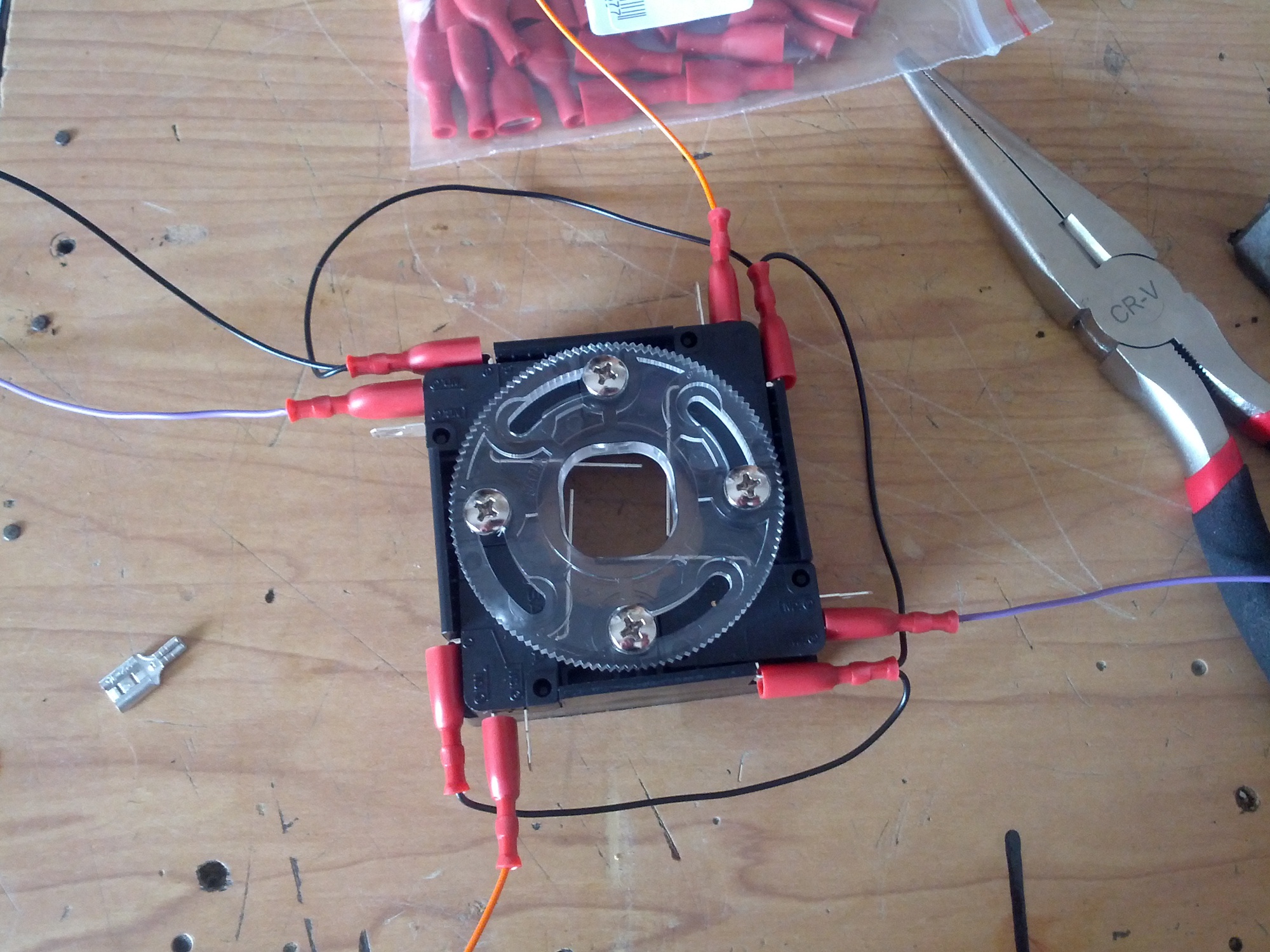
The buttons and joystick are Sanwa and cost a lot (50€ for 6 buttons and 1 Joystick...). I'll show them later, now we can start from the joystick that is a Sanwa JLW-TM-8.
Lets start from the screen, is a 7-inch LCD, found on ebay for 30€.
The buttons and joystick are Sanwa and cost a lot (50€ for 6 buttons and 1 Joystick...). I'll show them later, now we can start from the joystick that is a Sanwa JLW-TM-8.
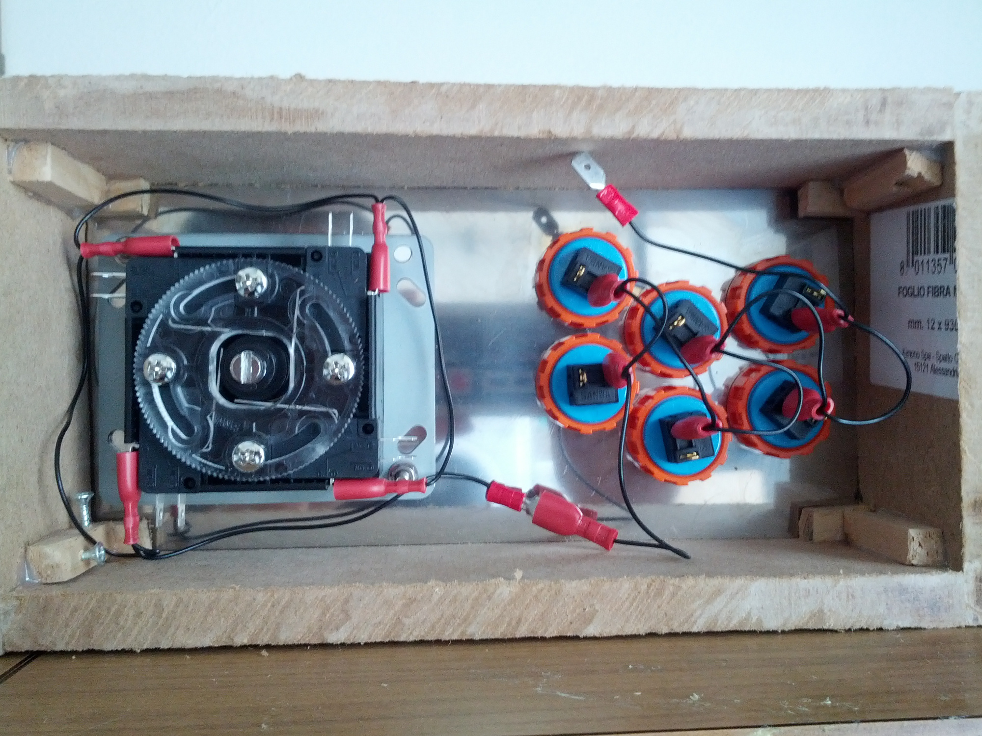
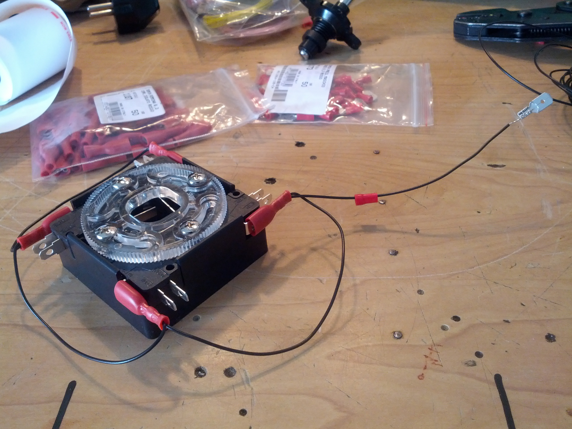 Above you see that I connected all the ground in a single cable, using the connectors to avoid having to solder contacts directly. Other contacts for the input are connected to individual wires of different colors.
Control Panel!
The Control Panel is arrived! It's made of laser-cut steel, 5mm thick.
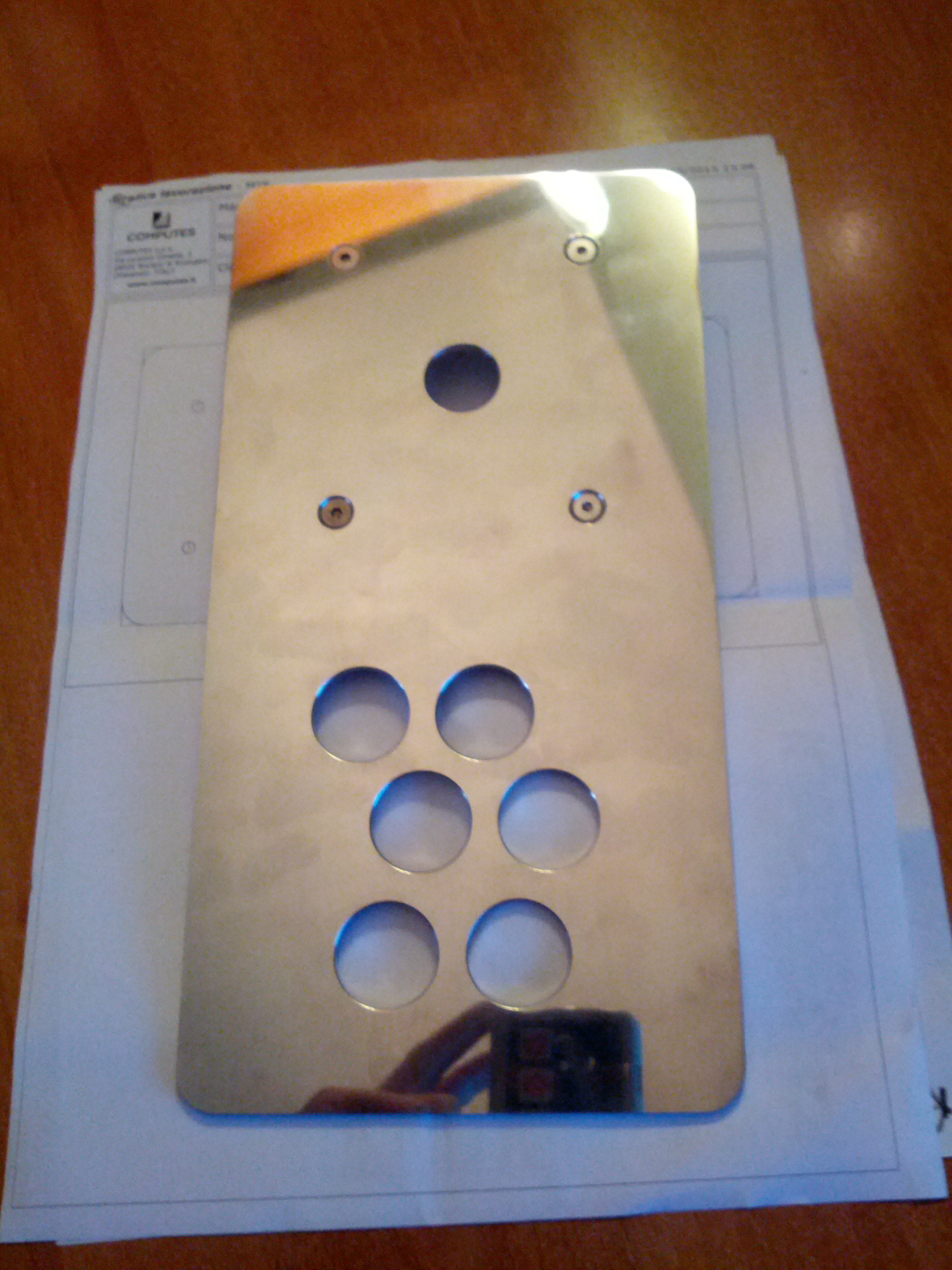
Here it is with the joypad and buttons in place, waiting to be wired!
First wiring...
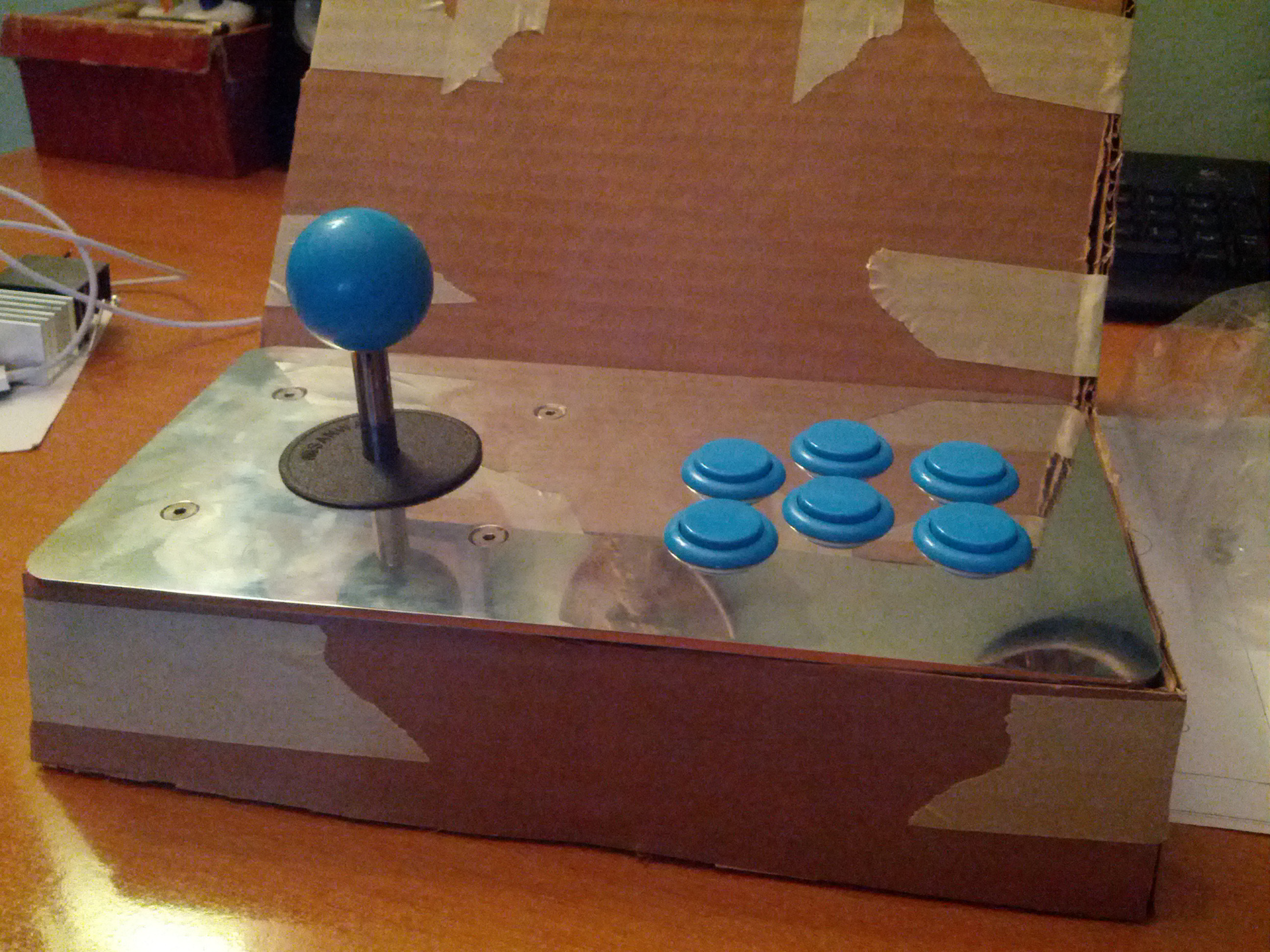
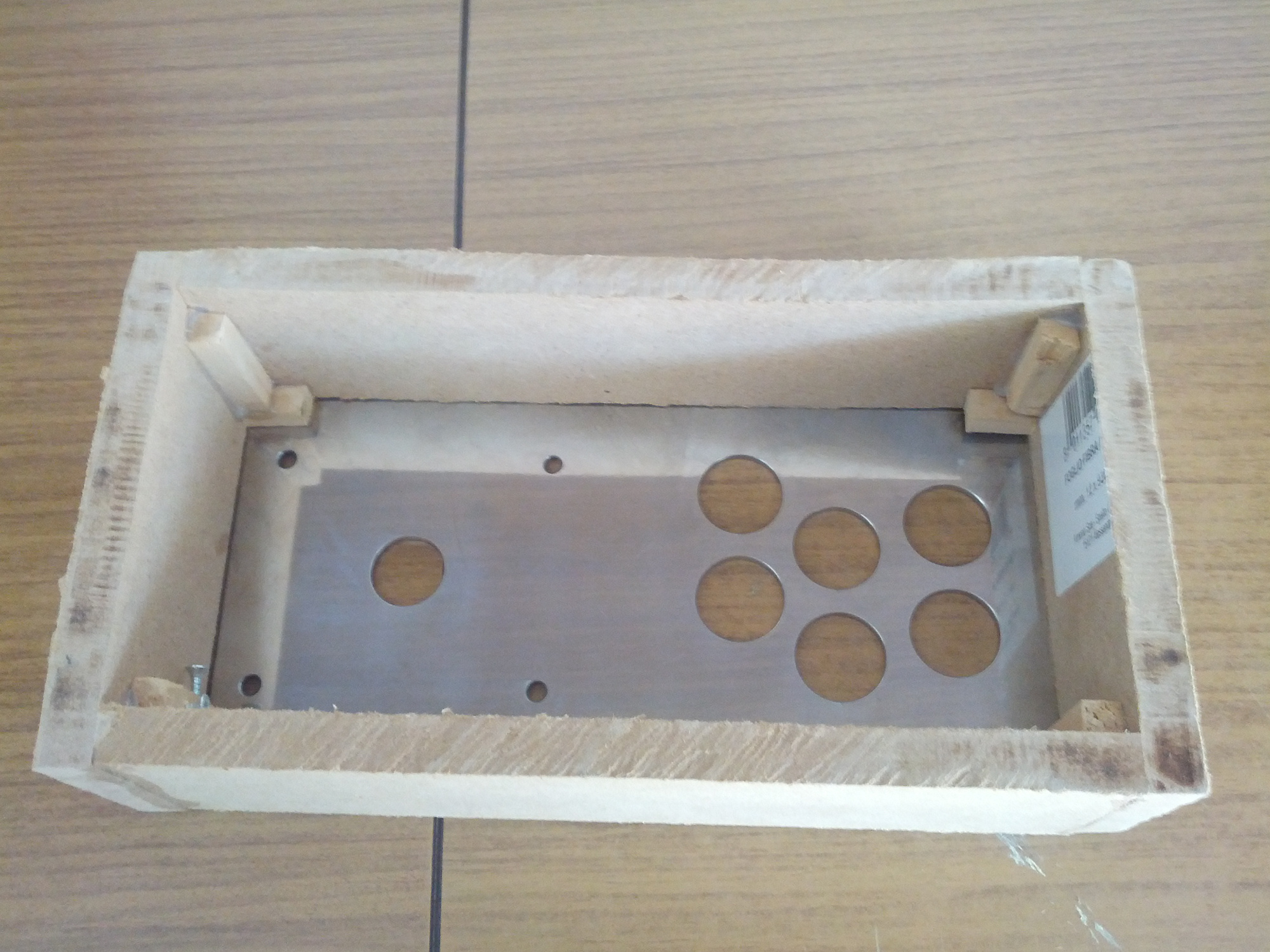
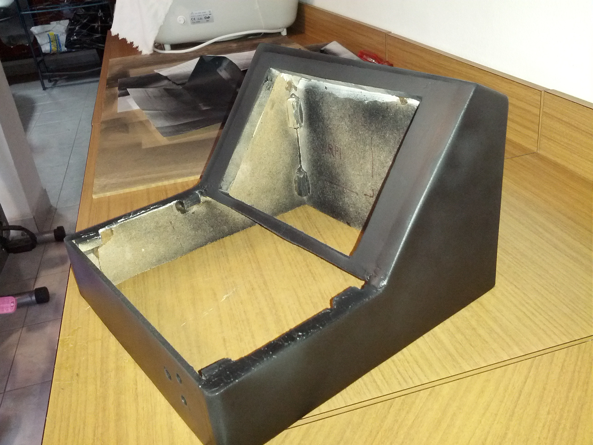
Since cutting the wood becomes long, I built a small box to carry out the wiring and software, and to check that the screws and glue work well
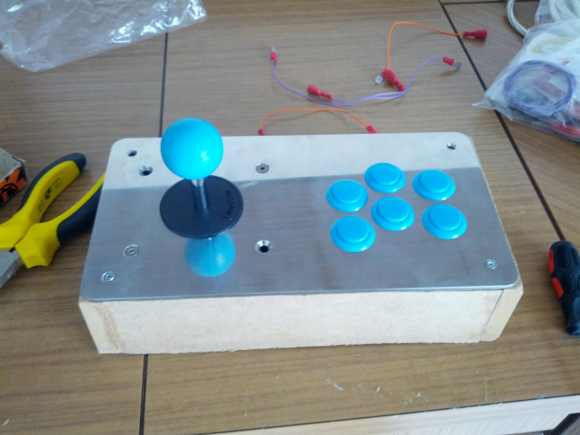
And here's what it looks like with the buttons mounted and the ground wired:
Now I am waiting for the arrival resistances etc. for connection to the Raspberry.
Raspberry-Control Panel connection
We have now reached the most important part, how to connect our Control Panel to the Raspberry using the GPIO.
Let's start with the electrical part:
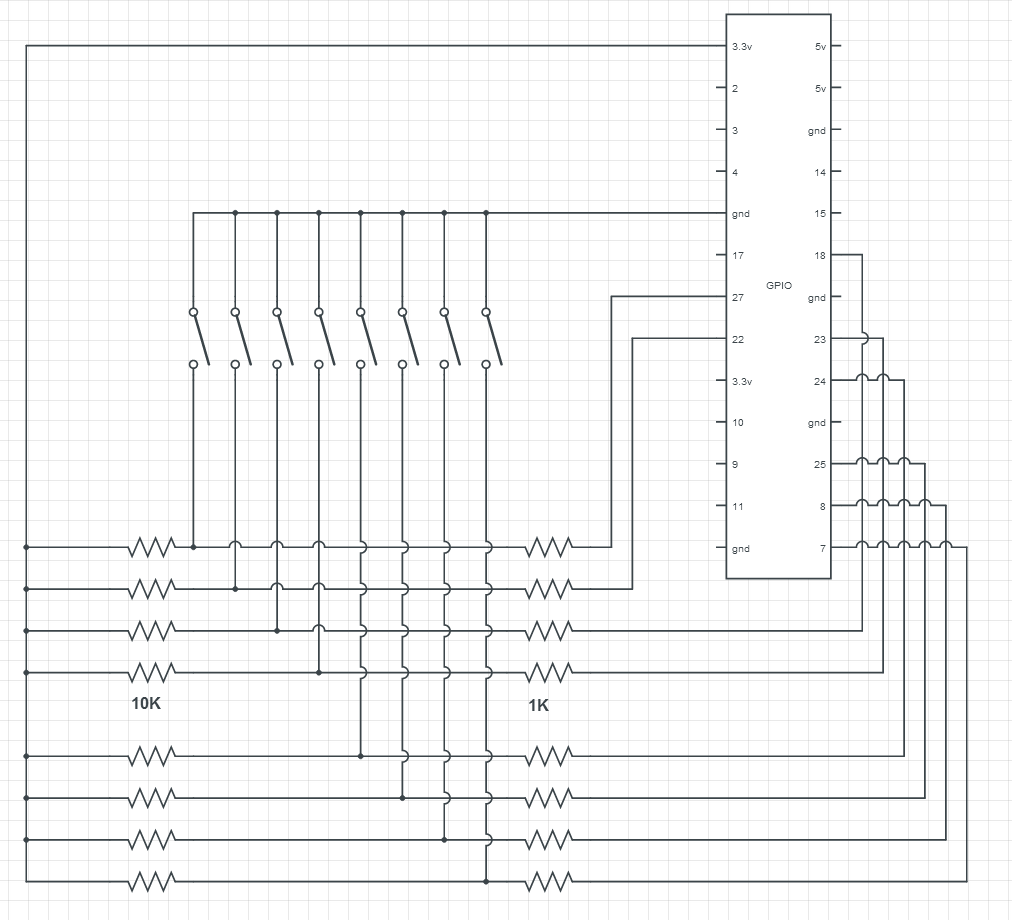
This is the circuit, as you can see it's very simple. Here illustrated there are only 8 keys, but the story is the same, we have to build a pull-down circuit connecting the GPIO to 3.3 V with two resistors in the middle. Doing this the GPIO will be detected in the HIGH state. Between the two resistors we put one side of our button, and to the other side we will connect the ground. Pressing the button will be so noted on a state LOW GPIO.
In my case I used 10k and 1k resistors. That 1k is not actually needed, but it is good practice to put it as protection in the GPIO.
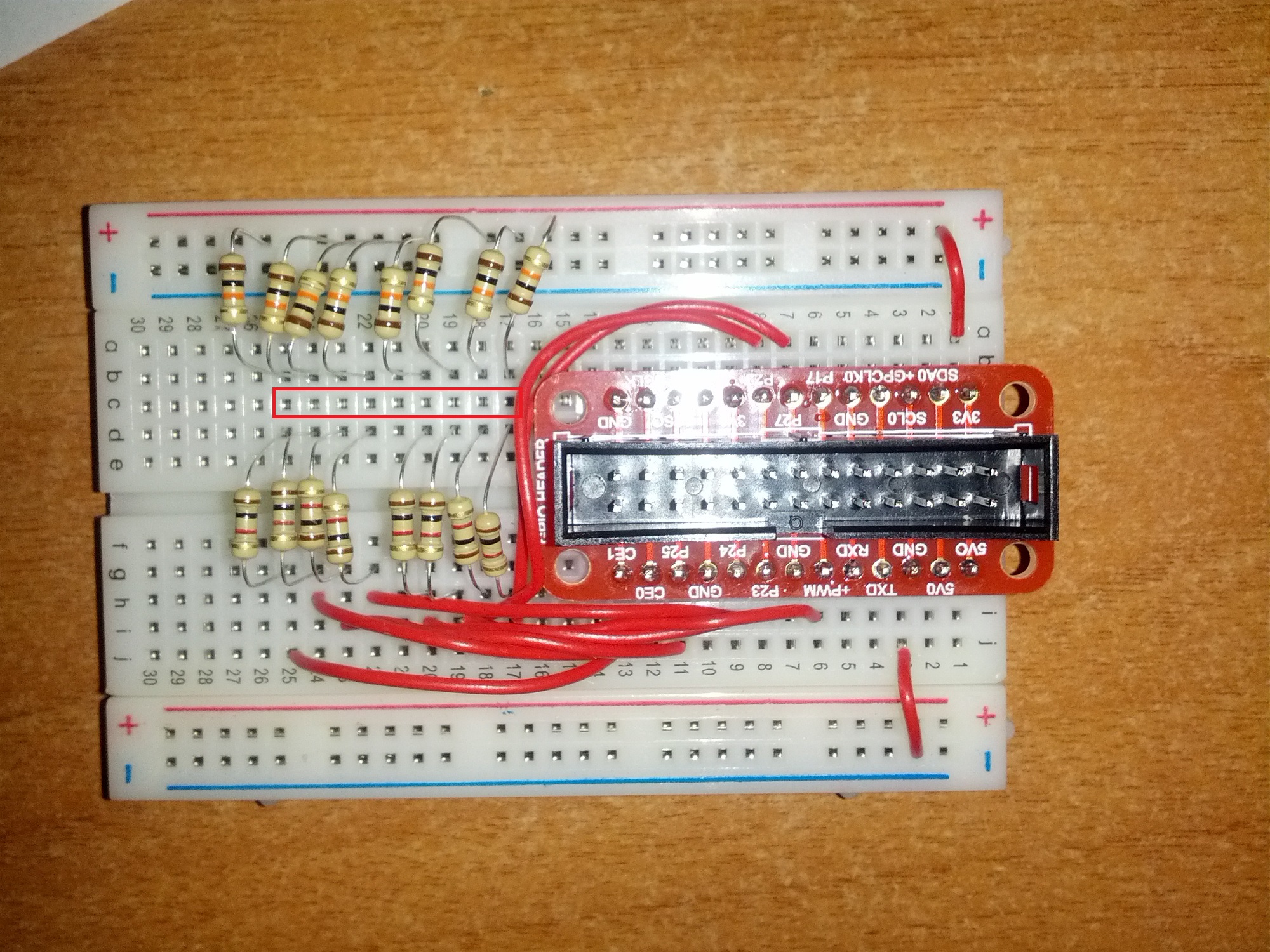
This is the circuit on the Bradboard. The button will be connected from one side to the holes marked in red, and the other to GND.
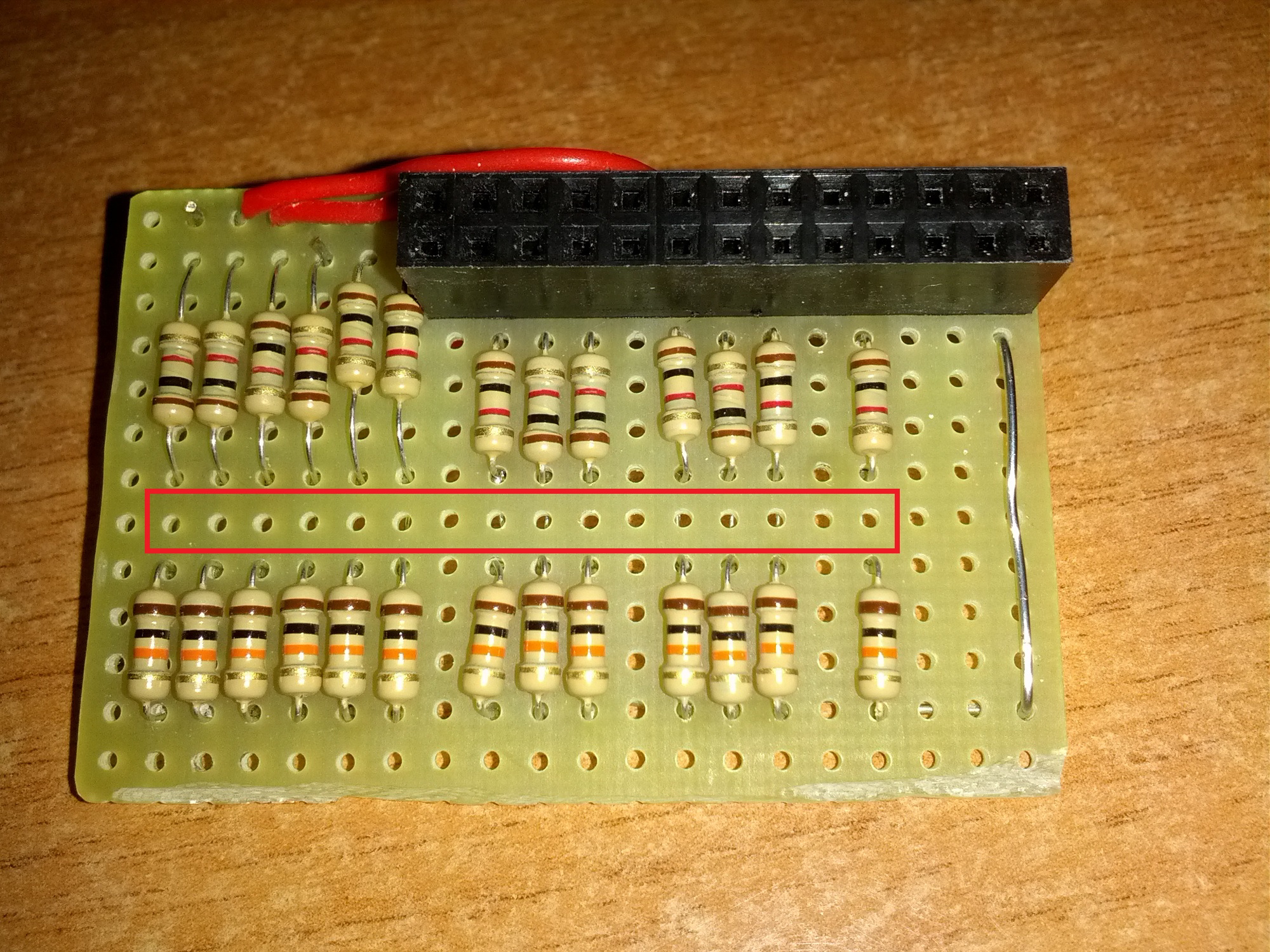
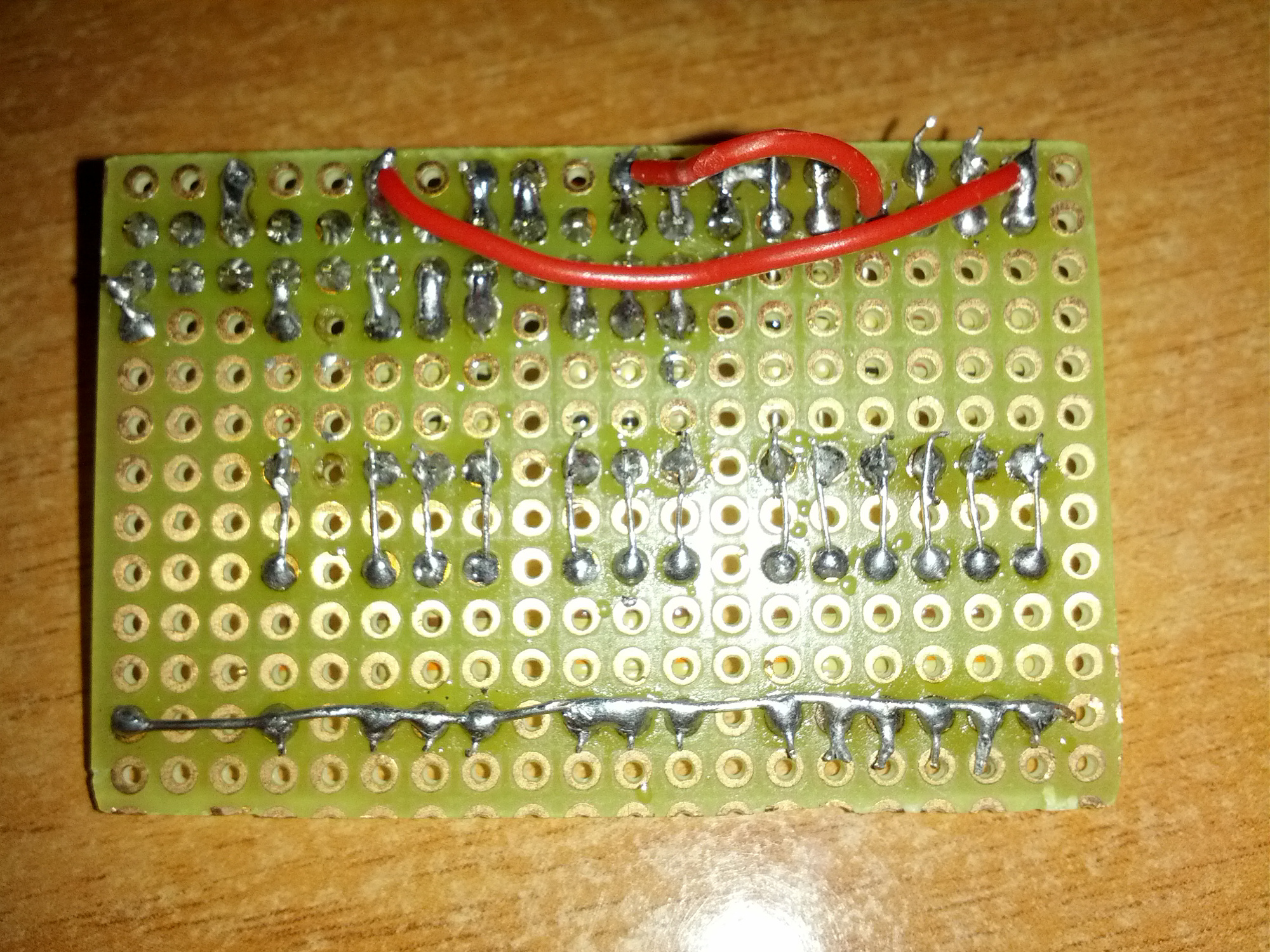
Here is my final circuit, with 13 button: UP, DOWN, LEFT, RIGHT, A, B, C, D, E, F, START, SELECT, ESC.
We come now to the software side.
For the connection, you must install Pikeyd.
You can follow the discussion HERE and the repository HERE.
Download the pack, extract it and compile with the make command.
Then edit the file /etc/modules as follows:
# /etc/modules: kernel modules to load at boot time.
#
# This file contains the names of kernel modules that should be loaded
# at boot time, one per line. Lines beginning with "#" are ignored.
# Parameters can be specified after the module name.
snd-bcm2835
uinput
joydev
12c-dev
Then open the file /etc/pikeyd.conf and configure the buttons as you want. The numbers that you see, are the GPIO to which the button is associated with.
This is my file, configure for the buttons D and C and the corresponding GPIO are missing:
KEY_LEFT 18
KEY_RIGHT 23
KEY_UP 27
KEY_DOWN 22
KEY_A 24
KEY_S 25
KEY_Z 8
KEY_X 7
KEY_1 10
KEY_3 9
KEY_ESC 11
To start at boot pikeyd then we have to add to /etc/rc.local this:
/usr/local/bin/pikeyd -d
To test the keys we can also try in the shell, in fact if we press the button, the letter associated appears not only to internal games, but in any point in the system.
Once we have tested our keys we can move on to the configuration of the games.
Some news...
First of all I finished painting the wood...
For the painting I opted for matte black, without giving the primer. You will notice a little difference between the wood and the filler, but i'ts not a bad job after all.
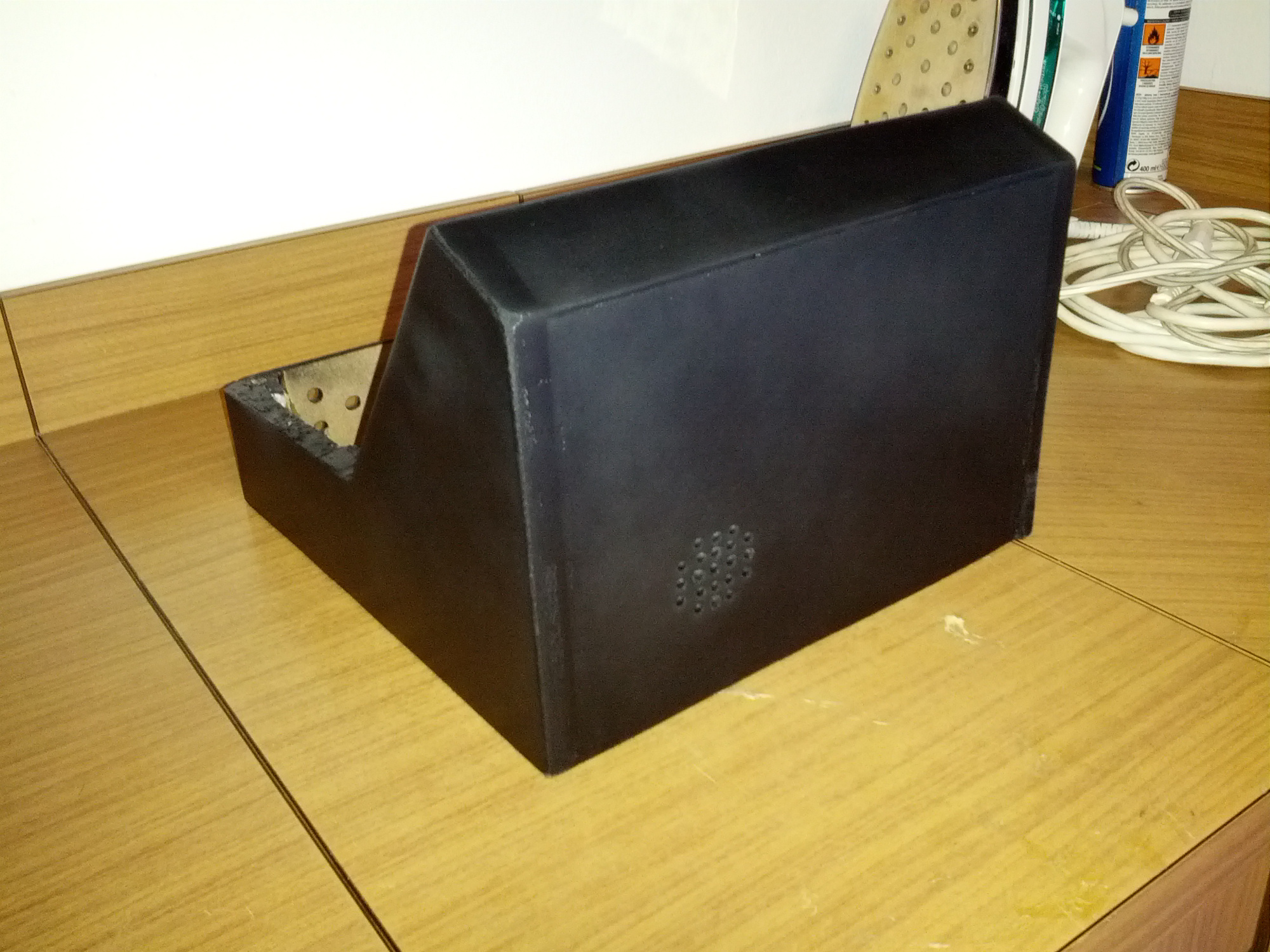
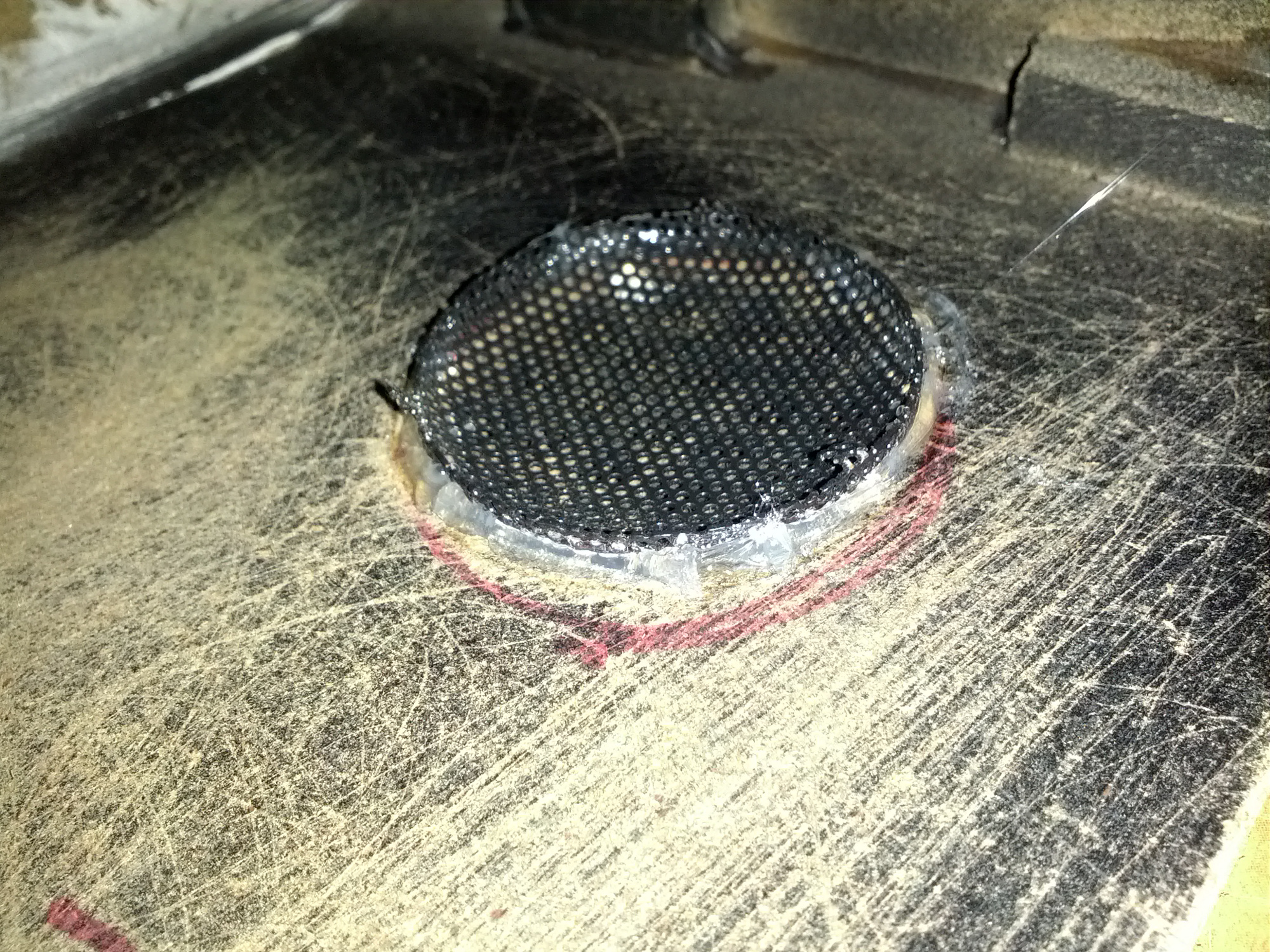
As you can see there are holes behind, for the audio speaker:
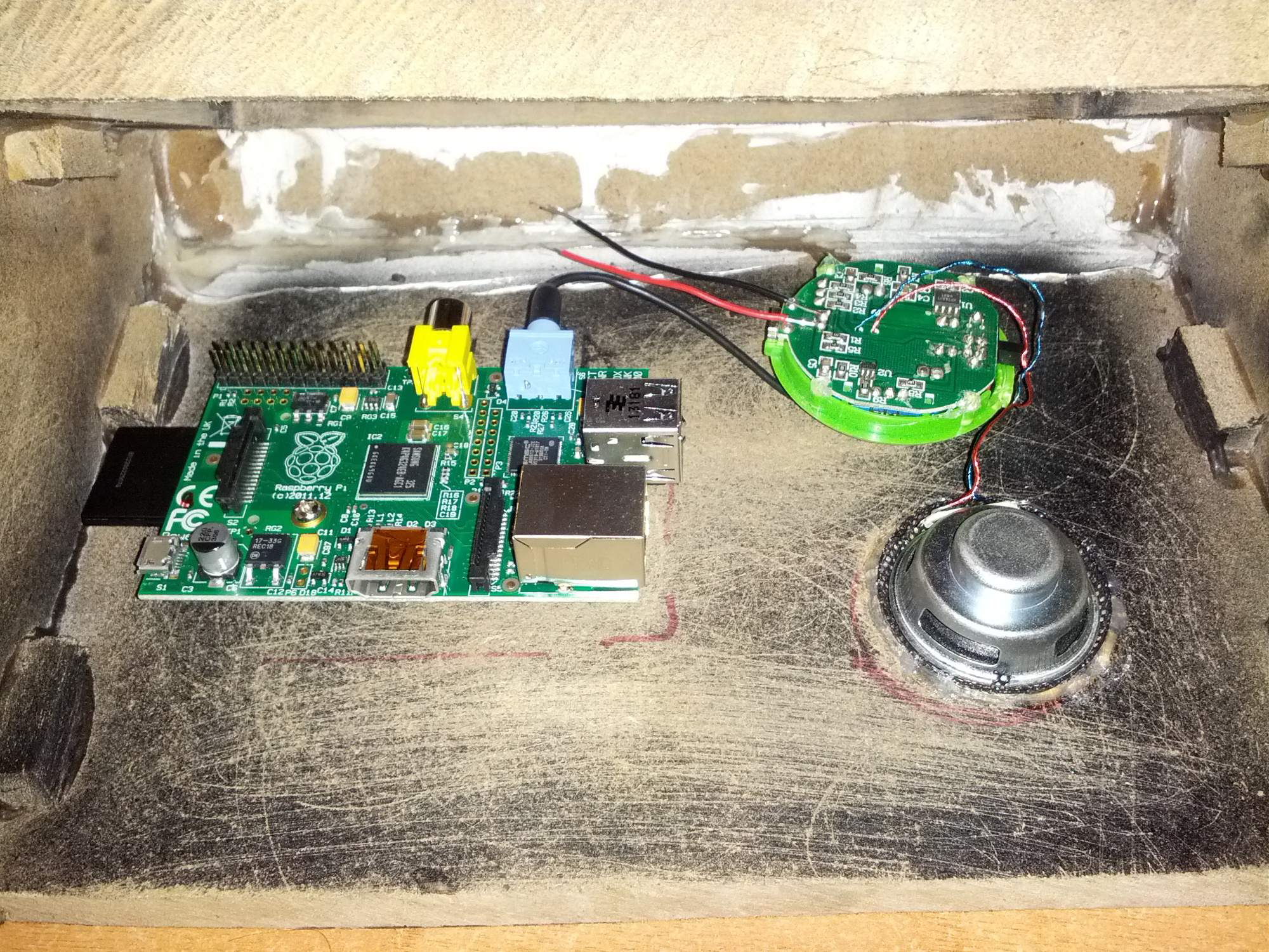
Here above you can see the position of raspberry on the left and on the right side the speaker's circuit.
As you can see the speaker is connected to the 3.5mm jack, while the 2 wires that I soldered above will be for power, always 5V. The speaker is one of those for mobile phone.
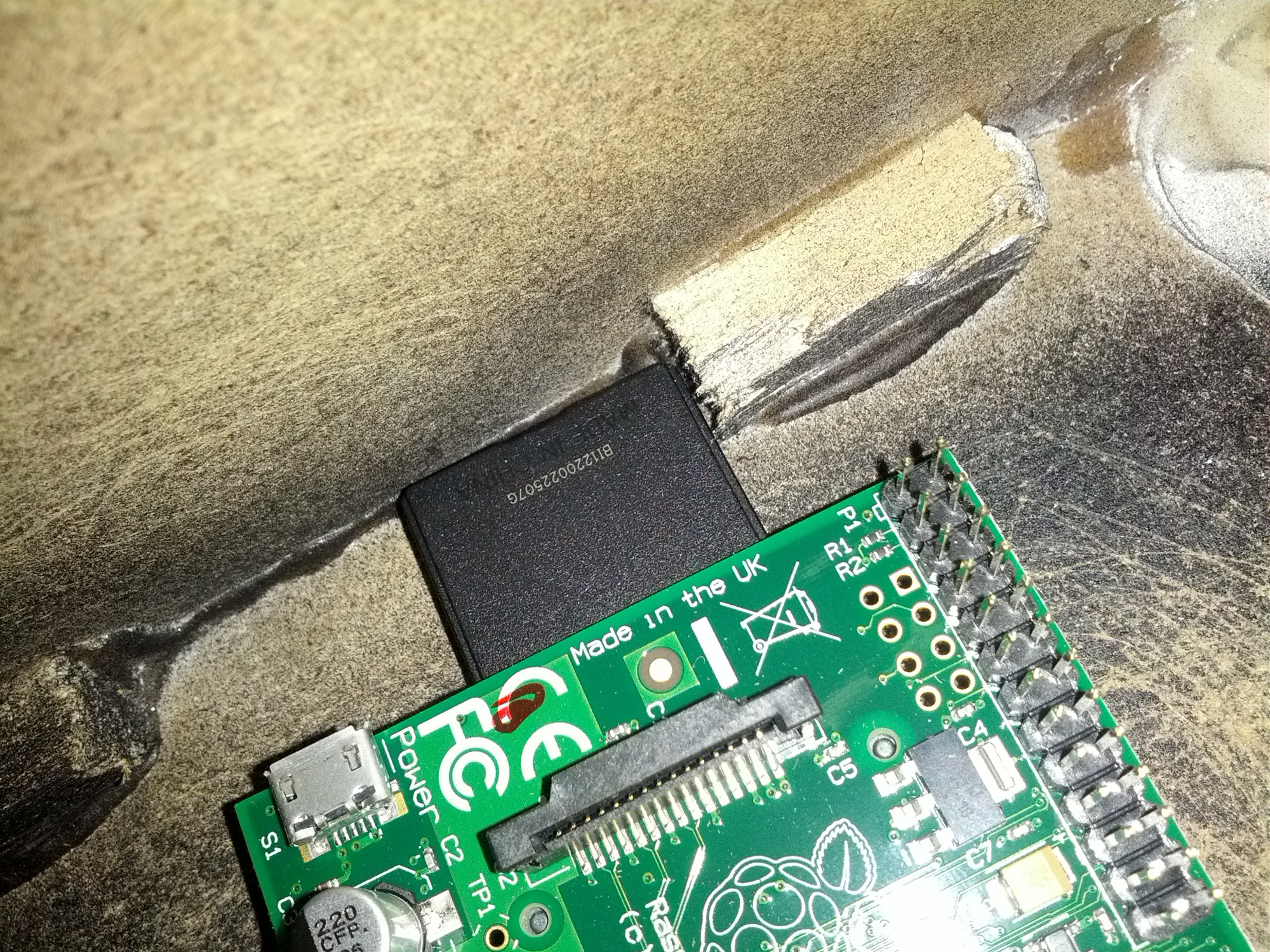
To fix the Raspberry to the wood I used the pins that are used to hold the motherboard to the pc case:

and this picture to tell you to never place the raspberry without first calculate the space for the sd card :D
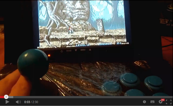
Video for you...in Italian, sorry :/
Cabinet ultimated!
And finally i finished my project!
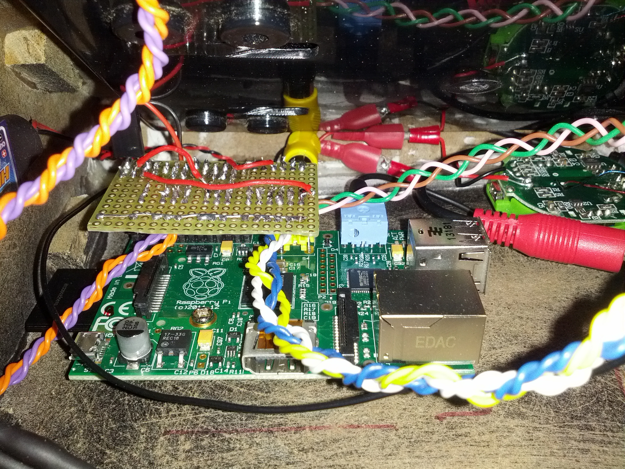
Here you can see the Raspberry in its place with the circuit connected to the buttons.
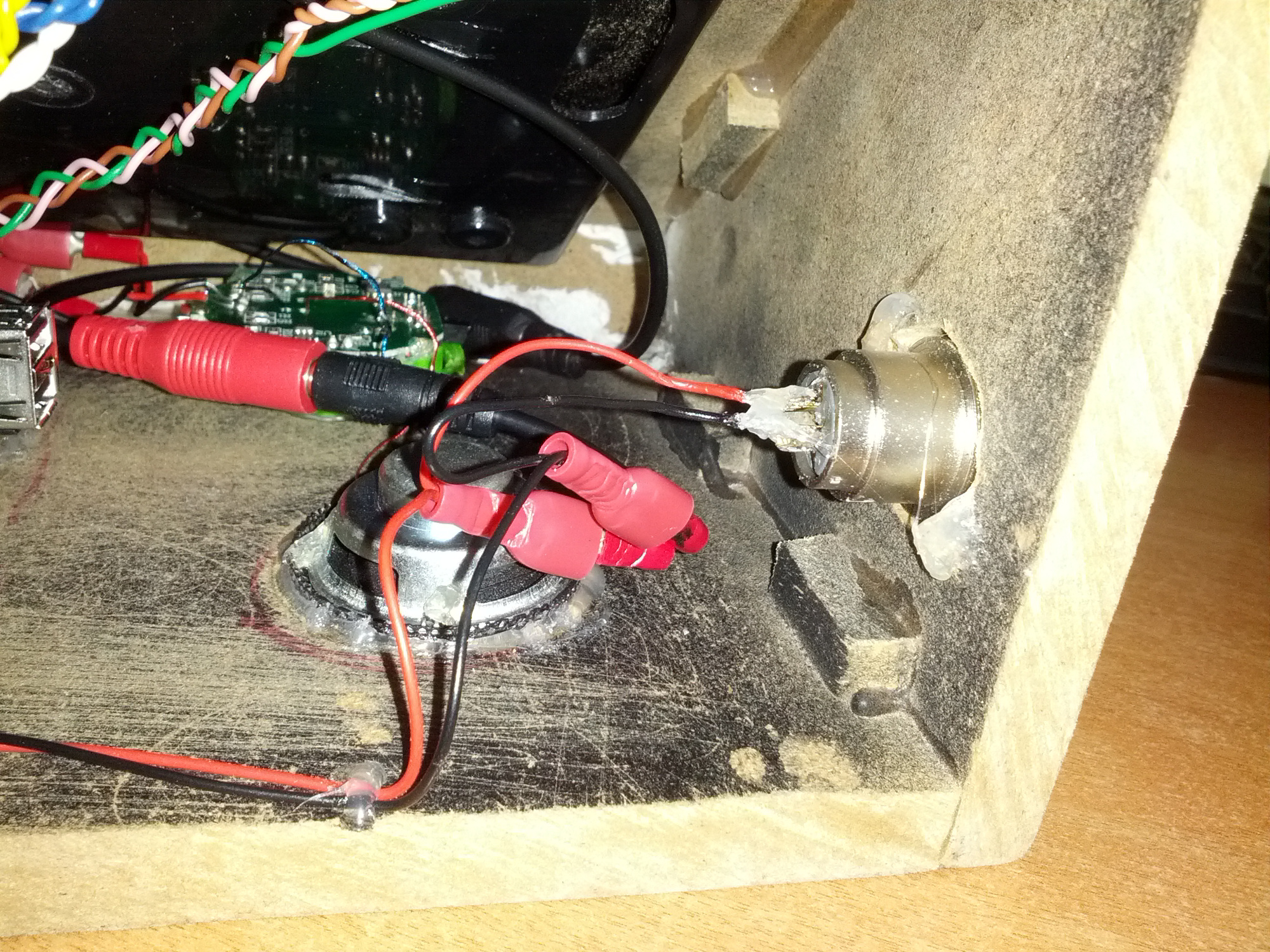
Here we see instead the audio speaker, connected via jack as already explained.
You can also see the power connector. It's a Canon connector, usually used for Microphone.
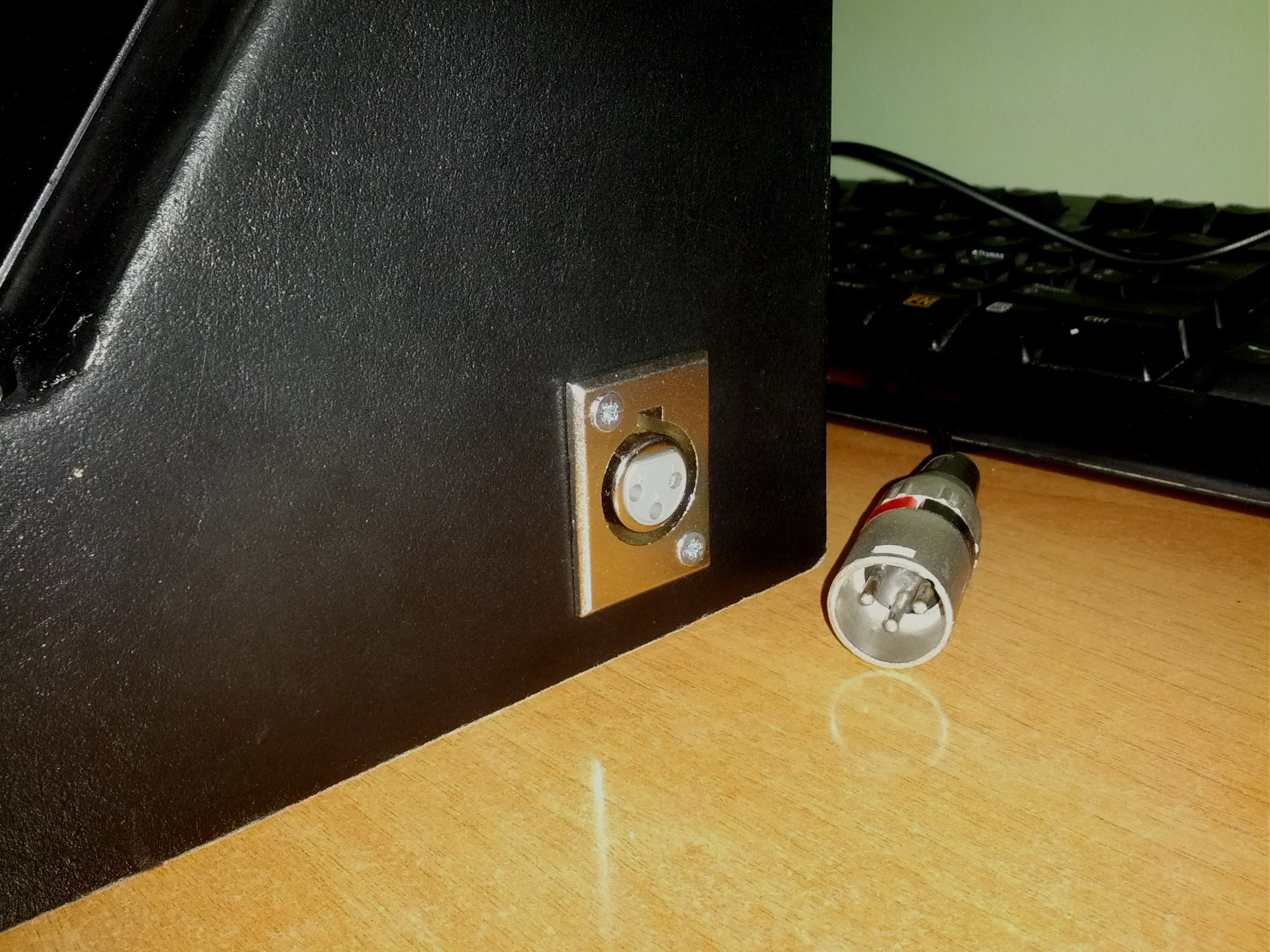
Here it is in the external part. This connector receive 12v directly via an external power supply.
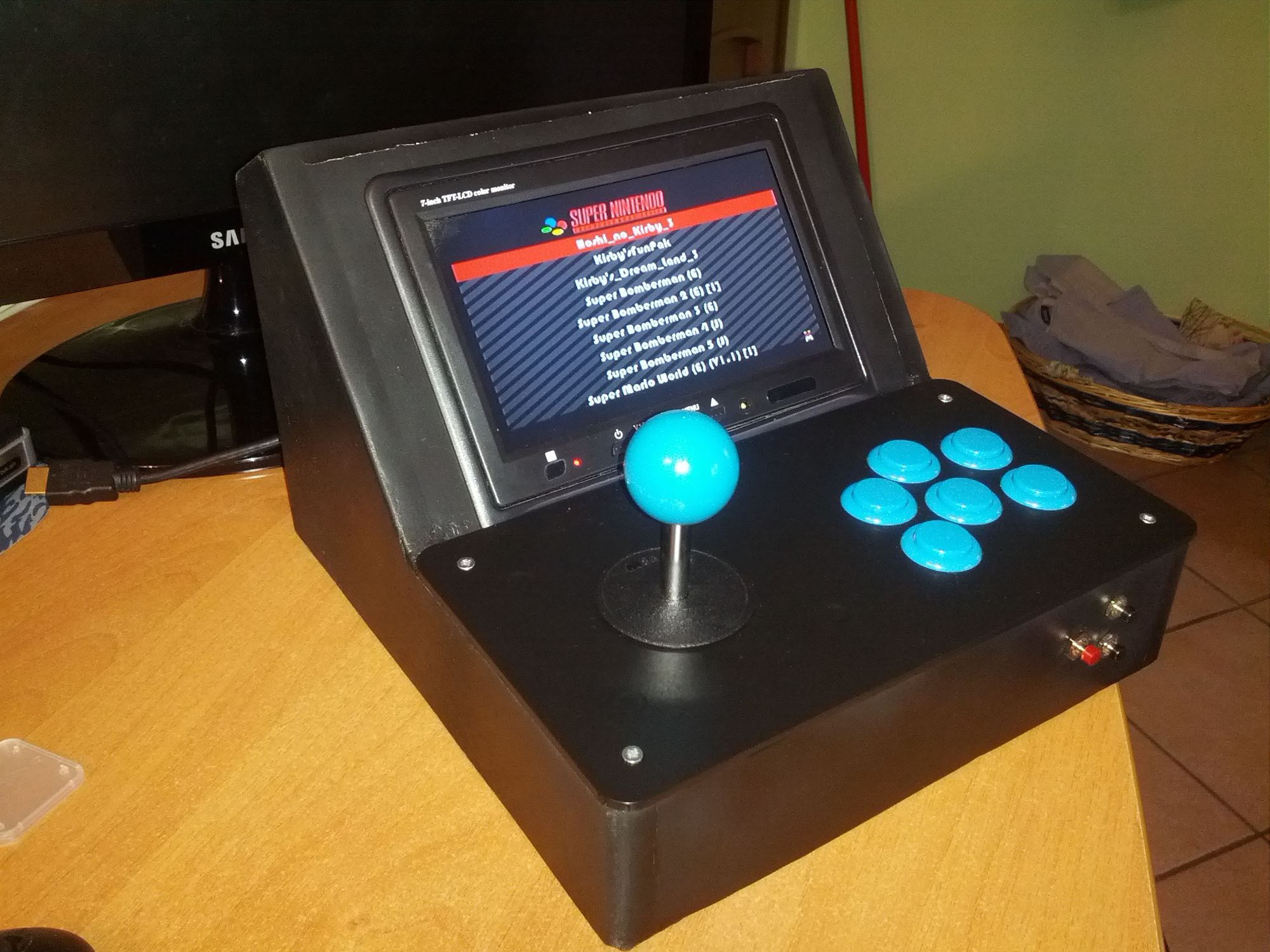
and here is the jewel completed!!
Some more Photos and a Video are coming
This is the circuit, as you can see it's very simple. Here illustrated there are only 8 keys, but the story is the same, we have to build a pull-down circuit connecting the GPIO to 3.3 V with two resistors in the middle. Doing this the GPIO will be detected in the HIGH state. Between the two resistors we put one side of our button, and to the other side we will connect the ground. Pressing the button will be so noted on a state LOW GPIO. In my case I used 10k and 1k resistors. That 1k is not actually needed, but it is good practice to put it as protection in the GPIO.
This is the circuit on the Bradboard. The button will be connected from one side to the holes marked in red, and the other to GND.
Here is my final circuit, with 13 button: UP, DOWN, LEFT, RIGHT, A, B, C, D, E, F, START, SELECT, ESC.
We come now to the software side. For the connection, you must install Pikeyd. You can follow the discussion HERE and the repository HERE. Download the pack, extract it and compile with the make command. Then edit the file /etc/modules as follows:
# /etc/modules: kernel modules to load at boot time.
#
# This file contains the names of kernel modules that should be loaded
# at boot time, one per line. Lines beginning with "#" are ignored.
# Parameters can be specified after the module name.
snd-bcm2835
uinput
joydev
12c-dev
#
# This file contains the names of kernel modules that should be loaded
# at boot time, one per line. Lines beginning with "#" are ignored.
# Parameters can be specified after the module name.
snd-bcm2835
uinput
joydev
12c-dev
Then open the file /etc/pikeyd.conf and configure the buttons as you want. The numbers that you see, are the GPIO to which the button is associated with. This is my file, configure for the buttons D and C and the corresponding GPIO are missing:
KEY_LEFT 18
KEY_RIGHT 23
KEY_UP 27
KEY_DOWN 22
KEY_A 24
KEY_S 25
KEY_Z 8
KEY_X 7
KEY_1 10
KEY_3 9
KEY_ESC 11
KEY_RIGHT 23
KEY_UP 27
KEY_DOWN 22
KEY_A 24
KEY_S 25
KEY_Z 8
KEY_X 7
KEY_1 10
KEY_3 9
KEY_ESC 11
To start at boot pikeyd then we have to add to /etc/rc.local this:
/usr/local/bin/pikeyd -d
To test the keys we can also try in the shell, in fact if we press the button, the letter associated appears not only to internal games, but in any point in the system. Once we have tested our keys we can move on to the configuration of the games.
Some news...
First of all I finished painting the wood...
For the painting I opted for matte black, without giving the primer. You will notice a little difference between the wood and the filler, but i'ts not a bad job after all.
As you can see there are holes behind, for the audio speaker:
Here above you can see the position of raspberry on the left and on the right side the speaker's circuit.
As you can see the speaker is connected to the 3.5mm jack, while the 2 wires that I soldered above will be for power, always 5V. The speaker is one of those for mobile phone.
To fix the Raspberry to the wood I used the pins that are used to hold the motherboard to the pc case:
and this picture to tell you to never place the raspberry without first calculate the space for the sd card :D
Video for you...in Italian, sorry :/


